For this project I've picked up few obsolete chips that have been sitting in a drawer for a long time waiting for occasion.
Clock's brain is based on PIC16LF876A microcontroller running at 10MHz.
Basically, only function of microcontroller is to monitor two buttons and occasionally read data from real time clock and display time and date.
Yes, it's too powerful chip for such a simple application but I prefer to have spare I/O pins and memory room in case I need to upgrade design or add some extra features.
Clock is showing current time by turning ON and OFF predefined number of LEDs of the same color. LED pattern is chosen randomly and microcontroller generates new LED pattern every second.
If button 1 is pressed clock shows current day and month in the same manner for a 30 seconds then switches back to time showing mode. Button 2 is used to activate time or date setting mode.
Real time clock is NJU6355 chip with 4-line serial interface and operating voltage 2 - 5V.
RTC is bundled with 32768 Hz watch crystal and 3V lithium coin cell battery CR 2032 as a backup power source. Battery is connected in series with diode and supplies 3V to RTC only when main power 5V is absent.
Controller assembled on a single sided PCB, made using heat toner transfer method, as usual;-)
 |
| Clock controller. PIC16FL876A. RTC NJU6355. |
 |
| Home-made PCB. Note load resistor for open drain input. |
Bright LEDs of 4 different colors (amber, green, red and blue) are organized into 3 x 9 matrix.
3 columns are controlled by dedicated 2N7000 low power MOSFETs.
Maximum DC current for this type of MOSFET is 200 mA and all 9 LEDs in a column can be ON simultaneously.
9 rows are connected directly to microcontroller's digital outputs.
Since it's only prototype, I've build ghetto LED matrix on a perforated board. All wiring is done by 24 gauge stranded wire.
 |
| LED matrix |
 |
| LED matrix wiring. |
Clock's button are normally open tactile switches.
Buttons inputs are pulled up by 10K resistors and microcontroller reads logic "1" (high level) when button's released and logic "0" when button's pressed.
LM7805 voltage regulator supplies 5V for whole unit. Since controller consumes low current and all LEDs are working in pulse mode, regulator stays cool and doesn't need any radiator.
 |
| Clock controller wiring. |
 |
| Controller and LED matrix connected together. |
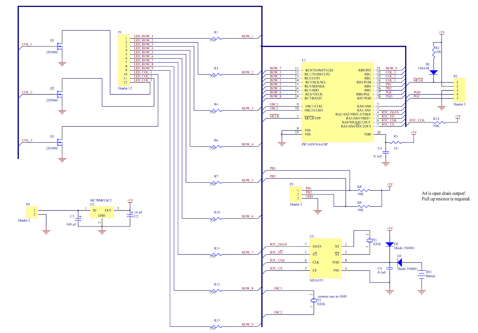 |
| Clock controller schematic. |
 |
| LEDs and buttons connection. |
Software source code download link.
(intro) <--- Wood block LED clock ---> (part 2)
No comments:
Post a Comment